 Українська
 English
Battery charge controller (КЗА)
Battery charge controller (КЗА)
The controller manages a stand-alone power system consisting of a battery bank, a charger, an inverter and an ATS circuit.
The controller can:
- monitor the battery voltage, with a digital display of the present battery voltage;
- control the charger and issue an inverter start/stop signal according to the state of the grid and the battery's depth of discharge;
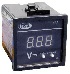
Distinctive features:
- The controller measures and displays the voltage applied to the "Usupply(meas)" input. The measured voltage also serves as the controller's supply voltage.
- To control the inverter, the controller has output contacts (a changeover group) marked "Inverter".
| 360 | |
| 48-420 | |
| 48-420 | |
| 1-999 | |
| 1-999 | |
| 0-999 | |
| 2 | |
| 2 | |
| 1 | |
| 10 | |
| 10 | |
- Nominal operating voltage (supply and measured), V
360
- Operating voltage range, V
48-420
- Adjustment range for Umax and Umin, V
48-420
- Adjustment range for the inverter switch-on delay, min
1-999
- Adjustment range for the inverter switch-off delay, s
1-999
- Adjustment range for the inverter on/off pulse duration, s
0-999
- Limits of permissible fiducial error for voltage measurement, %
±1
- Timing accuracy, better than, %
2
- Power consumption, max, W
2
- Permissible voltage between the supply (measuring) circuits and the relay output contacts, kV
1
- Mechanical life of the output contacts
107
- Electrical life at 6 A, 250 V AC, cos φ>0.95
10
5- Electrical life at 1.5 A, 250 V AC, cos φ>0.5
10
5- Maximum AC voltage switched by the output contacts:
250 V