 Українська
 English
30kVA.240VDC.220/380VAC SYNCHR/ATS/STS/BYPASS
30kVA.240VDC.220/380VAC/SYNCHR/ATS/STS/BYPASS inverter
30kVA.240VDC.220/380VAC/SYNCHR/ATS/STS/BYPASS inverter
Purpose:
- The inverter converts DC voltage into three-phase sinusoidal AC at 50 Hz.
- The inverter can supply a wide range of industrial and domestic loads rated 220/380 V AC at 50 Hz, up to 30 kVA for three-phase loads and up to 10 kVA per phase for single-phase loads.
- The inverter has a built-in automatic transfer switch (ATS) that transfers the load automatically between the mains incomer and the inverter according to the priority the user sets on the inverter's built-in controller.
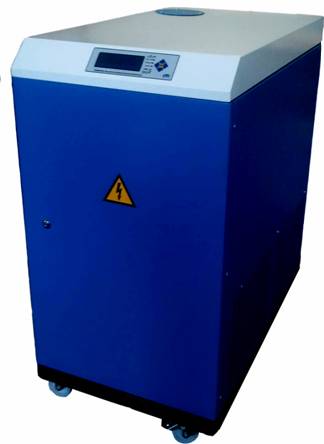
- The inverter has a built-in high-speed thyristor switch (static transfer switch) that transfers the load quickly between the mains incomer and the inverter.
- The inverter monitors the state of the battery and the mains and indicates input and output status.
Distinctive features:
- Pure sine wave output
- Silent, high-efficiency operation
- Apparent output power 30 kVA
- A high-efficiency combined liquid and air cooling system with four cooling levels and five automatic operating modes.
- The battery charge monitoring system extends battery life by reducing the number of charge-discharge cycles
- A control panel with a blue-backlit LCD showing the inverter's output currents and voltages.
- Six LED indicators show the inverter's status.
- Audible warning signals indicating the various operating modes, faults and system problems.
- Operating modes, the monitored battery and grid parameters, and the built-in ATS modes can all be programmed from the control panel.
- Inverter run/fail signalling relay
- Low standby consumption (under 20 W)
- Automatic overload and over-temperature protection
- Programmable deep-discharge battery protection
- Soft start with heavy loads
- Built-in high-speed thyristor ATS.
- Built-in automatic bypass that transfers the load to mains supply if the battery is fully discharged or absent.
Operating manual for the inverter
30kVA.240VDC.220/380VAC/ SYNCHR/ATS/STS/BYPASS
Variant
30kVA.240VDC.220/380VAC/SYNCHR/ATS/STS/BYPASS
Inverter apparent output power
30kVA
Inverter active output power
24kW
В
Ы
Х
О
Д
Type
Sine wave, total harmonic distortion ≤ 3%
Voltage
220/380V±5%
Current
Nominal RMS phase current — 46 A
Maximum permissible short-term RMS phase current: 68 A
Maximum peak phase current — 96 A
Frequency
50Hz±1%
Output voltage regulation
Total < ± 4% (0-100% load across the supply voltage range)
Overload 1
At more than 100% of rated load, when the thermal protection operates, the unit transfers automatically to mains supply.
Overload 2
At 120% of rated load, the unit transfers to mains supply automatically after 5 s.
Overload 3
At 150% of rated load, the unit transfers to mains supply automatically after 0.5 s.
DC input voltage
 (204 – 288) V
At Iload = (0.2 - 0.5)Cbat, Umin/cell = 1.7 V (Ubattery = 204 V)
Inverter shutdown on battery overvoltage (>288 V DC)
Inverter shutdown on battery undervoltage (< 204 V DC)
Battery bank
240 V, 400 Ah (two parallel strings of 20 × 12 V batteries, 200 Ah)
Mains voltage
220/380 V +10% -15%
Maximum permissible load power and current when running from the mains
42 kVA / 34 kW, 64 A, cos φ=0.8
Load supply interruption time
- transferring from battery to mains – no more than 70 ms
- transferring from mains to battery – no more than 70 ms
Transfer to mains on battery overvoltage, battery undervoltage and overloads 1, 2 and 3 must take place within no more than 70 ms.
Transfer to battery supply
- automatic, on loss of the mains supply.
- on the external "Start inverter" command.
If the inverter shut down because the battery discharged to Ures, the next transfer to battery must not occur until Ucharge is at least 273 V. The switch-on delay is 15 minutes.
Transfer to mains supply
- automatic, when the battery voltage falls below the Ustandby threshold and mains voltage is present;
- automatic, on inverter overloads 1, 2, 3;
- when the external "Start inverter" command is removed.
Main operating mode
Inverter priority with mains backup
External "Start inverter" command
Closing an external contact
Protection
Inverter shutdown on overload — yes
Inverter shutdown on overheating — yes
Inverter shutdown on a short circuit in the load — yes
Soft start with heavy loads.
If the maximum permissible current is exceeded, the inverter switches to load-current stabilisation, allowing the voltage waveform to depart from a sine wave (flattening of the sinusoid). This allows induction motors to start and other non-linear loads to be supplied during transient inverter operation without a protective shutdown.
A circuit breaker is fitted on the inverter's DC supply input
A circuit breaker is fitted on the inverter's AC output
Inverter status shown on LEDs or on an LCD display
Inverter running – green
Battery voltage low – red,
Overload – red
Inverter fault – red.
Load supplied from the mains – yellow.
Status of the circuit breaker on the inverter's DC supply input
Audible signals
"Battery low" audible signal, 0.5 s every second, when the battery is nearly exhausted (U < 321 V DC)
An audible signal of 0.5 s every 4 s after the battery has been disconnected.
A continuous signal on any inverter fault and at loads above 100%..
Efficiency at rated load
>90%
Noise level