 Українська
 English
КЗА1
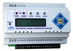
Battery charge controllers КЗА1.120, КЗА1.240, КЗА1.360, КЗА1.480
Battery charge controller (КЗА1.120, КЗА1.240, КЗА1.360, КЗА1.480)
 Purpose and principle of operation:
- The controller monitors battery condition in stand-alone power systems.
- The controller provides:
- monitoring of the total battery string voltage, the voltage of each battery, the current flowing through the batteries and the total charge;
- issuing control signals according to the battery string voltage and the voltage of each battery;
-programmable pickup thresholds and time delays;
- measurement and display of the present total voltage, the voltage of each battery, and battery current and charge;
-LED indication of battery status.
- The controller is housed in a DIN-rail case, with the supply conductors connected via terminal blocks.
- The controller is connected to each of the series-connected batteries (see the wiring diagram in the operating manual). The measured voltage also serves as the controller's supply voltage.
The controller's total nominal voltage is 120 V, 240 V, 360 V or 480 V depending on the version.
- Nominal voltage supplied from the measuring shunt — 75 mV.
- To output control signals the controller has relay contacts (changeover groups) "К1" and "К2". Relay "К1" picks up when the total voltage and the voltage of each battery are within limits. If any monitored voltage goes outside the set thresholds, relay "К1" drops out. Relay "К2" is not used in version v01.
- By agreement, versions with an RS485 or RS232 interface, MODBUS protocol, and a built-in GSM/GPRS modem can be supplied.
- The adjustment ranges for the maximum and minimum voltage thresholds of the battery string (Ubat) and of the individual cell (Ucell), the setting range for the measuring shunt current, and the adjustment range for the switch-off and switch-on times are given in the table.
| Versi on | ||||||||
Versio
sion
Qty
battery
Ubat, V
max.
Ubat, V
min
Ucell, V
max.
Ucell, V
min
I, A
shunt
t, s
off
t, s
on
КЗА1.120
10
0-299
0-299
0-19,9
0-19,9
0-99,9
1-999
1-999
КЗА1.240
20
0-399
0-399
0-19,9
0-19,9
0-99,9
1-999
1-999
КЗА1.360
30
0-499
0-499
0-19,9
0-19,9
0-99,9
1-999
1-999
КЗА1.480
40
0-599
0-599
0-19,9
0-19,9
0-99,9
1-999
1-999
- Limits of permissible fiducial error for voltage and current measurement: ±1% of nominal
- Timing accuracy: better than 2%
- Power consumption: no more than 2 W
- Permissible voltage between the supply (measuring) circuits and the relay output contacts: 1 kV
- Mechanical life of the output contacts: 107
- Electrical life at 10 A, 250 V AC, cos φ>0.95: 105
- Maximum voltage switched by the output contacts, AC: 300 V
- Conductors connected via terminal blocks; conductor cross-section 0.35-1.5 mm2
- Overall dimensions 140×115×65 mm
- Time to initial readiness after power-up: 3 s
- Weight: 350 g.
- Operating temperature range: -25 - +55 °C
- Protection rating per ДСТУ ГОСТ 14255:
-enclosure IP 40
-connector IP 20
- Service life at least 10 years
Description of operation, calibration and programming of the КЗА1